How to identify thread size and pitch in fluid applications: A Primer
By Joel Martin, Swagelok Company
Features fittings fluids pitch primer Swaglok thread size
In a properly functioning industrial fluid system, every component must work together to deliver fluids, leak-free, to their final destination. The safety and productivity of facilities hinge on everything being in perfect working order.
Therefore, it is important to select correctly sized fittings for fluid system end connections — and install them properly. Reliable operation hangs in the balance. Chosen well and installed properly, the right fittings will not leak and will hold beyond the burst pressure of the tubing.
Proper Identification Allows Fluids to Flow Leak Free to Their Final Destination
Ensuring your facility is using the correct fittings begins by educating your team about the proper thread size and pitch for each fitting.
The Basics
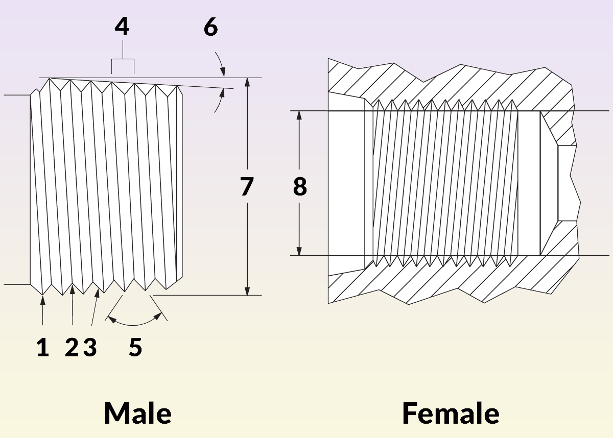
Figure 1. The following terms for male and female end connection threads are important to understand to grasp the basics of thread identification:
1. Crest
2. Root
3. Flank
4. Pitch
5. Thread flank angle
6. Taper angle
7. Male thread OD (outer diameter)
8. Female thread ID (inner diameter)
Identifying threads is not easy, even for someone with years of familiarity with threaded components. Before classifying specific threads, you should understand a handful of terms so you can grasp the basics of thread identification (Figure 1).
- Thread Gender: Whether a thread is male or female depends on where the threads are on the fitting. Female threads appear on the inside of fittings, and male threads appear on the outside. Male fittings thread into female fittings.
- Pitch: The distance between threads is called the pitch. It can be measured in either threads per inch or millimeters, and it relies on specific thread standards (NPT, ISO, BSPT, etc.).
- Crests and Roots: Crests and roots are the peaks (crests) and valleys (roots) of the threads, while the flat surface in between is referred to as the flank. The thread flank will have a specific angle that will factor into the proper fitting selection.
How to Identify Thread Types
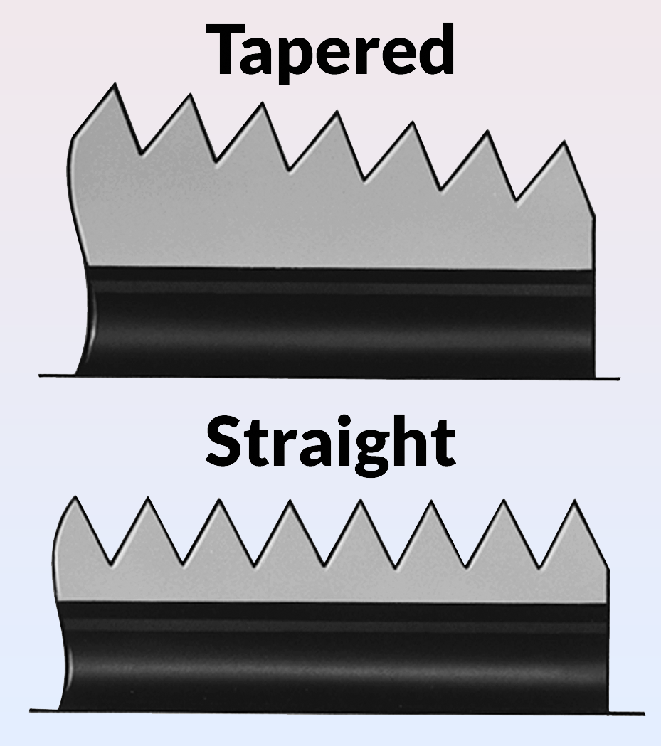
Figure 2. Tapered threads, which are also called dynamic threads, seal themselves as the flanks of the male and female threads join together. Straight threads, on the other hand, must have other mechanisms (such as a gasket, O-ring, or metal-to-metal contact) to aid in creating a leak-tight seal.
To properly identify the thread size and pitch, it is important to have the proper equipment, which includes a calliper, pitch gauges, and a thread-identification guide. The first necessary identification trait to determine is whether the threads are tapered or straight (Figure 2).
Straight threads, also known as parallel threads or mechanical threads, do not seal anything. They are designed to keep a nut on the body of a tube fitting. Instead of sealing themselves, they must work in concert with other mechanisms that aid in creating a leak-tight seal, such as a gasket or O-ring, or via metal-to-metal contact.
Tapered threads, which are also called dynamic threads, seal themselves as the flanks of the male and female threads join together. It is important to include a thread sealant or thread tape in such assemblies to fill in the gaps between the crests and roots to eliminate leaks at the junction of the two fittings.
Straight threads run parallel to the centreline, while tapered threads are angled in relation to the centreline. Technicians should use callipers to measure the diameter on the first, fourth, or last full threads from crest to crest. If the diameter remains the same on all the threads, you have straight threads. If the diameters decrease or increase, you are working with tapered threads.
Measuring Thread Diameter

Figure 3. To determine the diameter – or the distance between the two crests in a thread – a caliper is the tool of choice.
After determining whether you have straight or tapered threads, it is important to measure the diameter of the threads. Use a calliper to calculate the distance between two crests (Figure 3). In the case of straight threads, you can measure the distance at any full thread. For tapered threads, however, it is important to take the measurement at the fourth or fifth full thread.
Keep in mind that it is possible the diameter measurement you get may not coincide with the nominal size for the given thread. The difference is likely due to slight variations in industry or manufacturing tolerances. If you use the fitting manufacturer’s thread identification guide, you should be able to get the diameter as near to the right size as possible.
Determining Thread Pitch
After determining the thread diameter, you can measure the thread pitch using a pitch gauge (known alternatively as a thread comb). Measure the thread against each pitch gauge form until there is a perfect match (Figure 4). Fractional and metric thread forms can be extremely close, so it may take some time to decide on the perfect fit.
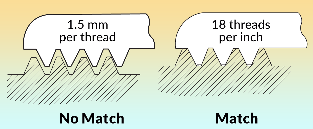
Figure 4. Measure the thread against each model until there’s a perfect match. Fractional and metric thread forms can be extremely close, so it may take some time to decide on the perfect fit.
Deciding Which Thread Standard Applies
The last step in thread identification is to determine which thread standard applies. Once you have determined the thread’s gender, type, nominal diameter, and pitch, a thread identification guide – typically provided by the fluid system component manufacturer – will allow you to figure out which standard applies.
Identifying the End Connection
Finally, you will need to choose the right end connection. Use a manufacturer’s thread identification guide to locate the range of available end connections that have either the tapered or straight thread you identified. Then, study the cross-section drawings for these end connections and determine which one matches your application. Use a seat gauge tool – which typically includes gauges for seat angles of 45°, 37°, and 30° – and place its angle against the seat angle of the end connection. If the centre line of the fitting and the longitudinal axis of the gauge are parallel, the seat angle and the gauge angle are the same. If not, try another gauge.
As noted above, the thread identification process can be a challenge. These tips should help you succeed in making proper identifications so you can choose the right fittings to allow fluids to flow leak free to their final destination. In addition, working with a capable fluid systems supplier can help make this process much easier, especially when the supplier offers hands-on training courses to get your staff up to speed.
Joel Martin is Manager, Commercial Training & Services for Swagelok Company. An original version of this article appeared on the Swagelok Reference Point blog here.
Print this page